|
LPI Lightning Protection Definition and Provision of Area of Protection |
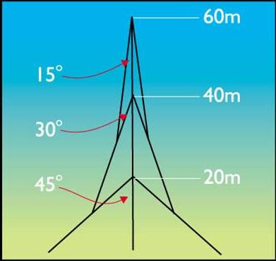
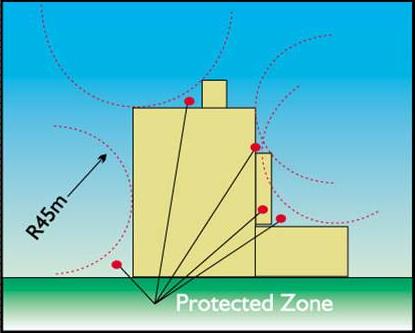
The conventional Methods
Electric Field Modelling
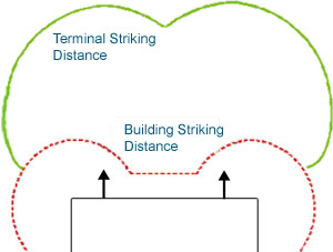 |
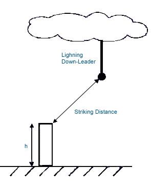
Striking distance is influenced by geometry and dimensions such as height, width, radius and altitude all have effect. Corners and edges cause an up-leader to be launched when the down-leader is at a greater distance than do flat surfaces. This striking distance is calculated for all directions from the terminal and from the structure resulting in two surfaces. |
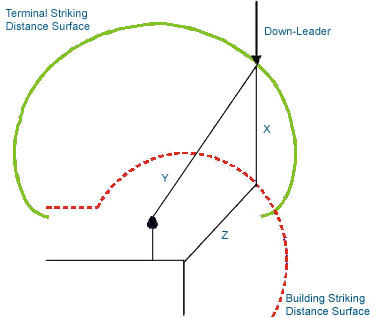 | The software determines if coverage is successfully achieved based on the relative distances between the surfaces and typical leader velocities based on the site & location conditions |
 |
Placement Method Originally developed by AJ Ericksson LPI CAD software forms three dimensional representation of the structure to be protected and the air terminals to be used. Based on this representation the software determines if protection is achieved to the required level of risk. |
LPI Guardian System 5
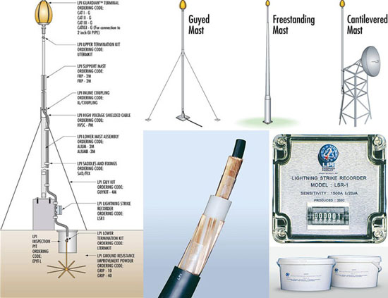
1. Family of LPI CAT series air terminals
2. FRP insulated mast for mounting of LPI CAT series air terminal
3. LPI High Voltage Shielded Cable (HVSC) to safely conduct the energy
4. LPI Lightning Strike Recorder (LSR)
5. Grounding system including GRIP and Exothermic welding
- LPI Guardian Terminals
- CAT Air Terminal
- LPI Stormaster ESE Terminals
- LPI HVSC Down Conductor